-
Notifications
You must be signed in to change notification settings - Fork 45
Wireless (Optional)
For an optional wireless build, there are a few extra steps:
- the capacitor
- the battery
- the power switch
You can also leave off the TRRS connector if desired.
I would do all the soldering with the MCU off the board.
First, solder the decoupling capacitor while there are no battery wires in the way.
The capacitor goes along the board edge under the USB connection.
It is shown here between the two battery wires.

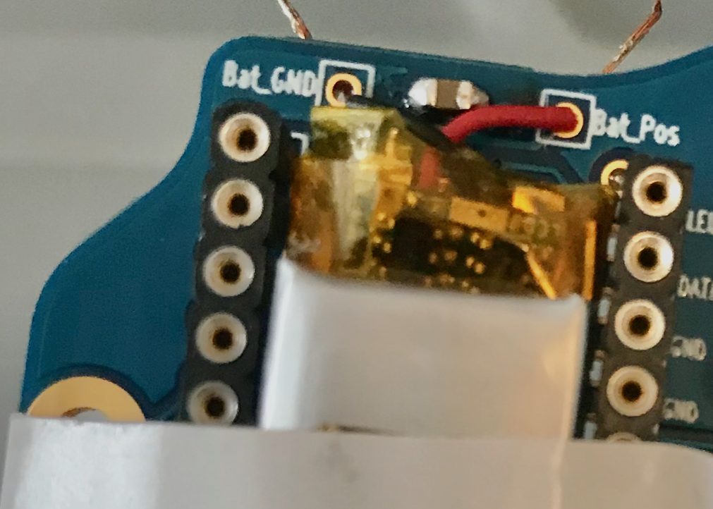
Wiring the battery leads is delicate. They can be wired to the pads along the board edge or to the pads at the bottom end of the MCU. The images here show soldering to the pads along the board edge. But, the pads at the bottom end of the MCU give more clearance between the battery's circuitry bump and the MCU's USB bump.
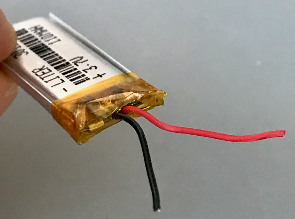
Cut off any plug on the end of your battery wires. Be careful not to short the wires together while cutting, trimming, handling or soldering.

Place the battery between the MCU sockets and judge how much you want to trim the wires.
One approach is threading the wires through the pad holes, leaving and bending over a bit extra, and soldering from the bottom side. Going through the pad helps get the wires to stay in place while soldering. You can always trim a bit more, but you can't untrim. Trim each wire separately, not together. Strip the insulation off the part of the wire that will go through the board, but leave the insulation on the part that will remain on top of the board. Tinning each wire can help inserting through the pad.
Your lengths should be similar to these. The length below the board is longer than needed here, but will be trimmed after soldering.

It can help to hold the battery down with a bit of tape while you solder on the bottom side of the PCB.
Once you have the wires trimmed, striped, though the pads, and the battery taped down, turn the board over and solder the wires to the battery pad. Then trim off the excess wire.
Finally, solder the power switch. It goes just above the upper thumb key with the knob next to the board edge.
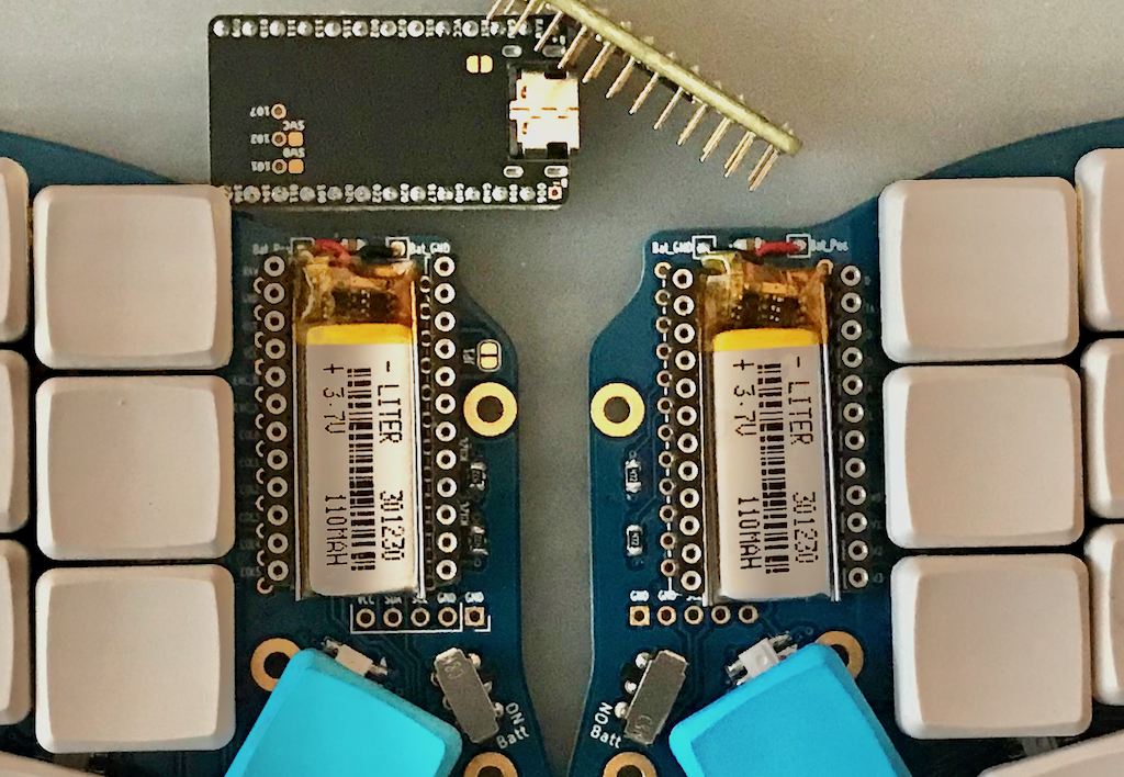
Your board should now look like this if you soldered to the top pads. Minus the key caps and switches, which you should wait until after testing to put on. The newer board version offers the lower battery pad option as well, so your board likely has extra battery pads between the MCU and thumb keys, which you may have used.

Next: Reset (Optional)